KÜRESEL VANA
PRODUCT FEATURES
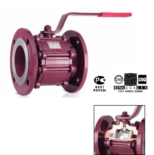
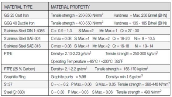
- GG 25 cast iron body and flange.
- Stainless steel sphere.
- Stainless steel belleville spring reinforcement.
- PTFE, sphere sealing ring, outer sealing ring and stem ring.
- Additional sealing quality is achieved by mounting the stem internally, supported by PTFE and O-Ring system.
- Flanges are according to ISO 7005 – 2.
- Valve mounting dimensions acc. to DIN3202 F4.
- Available in two types: Full-Bore and Reduced-Bore
- Easy to use.
- Longer service life.
- PN 6 ball valves can easily be connected to circulation pumps, without any additional fittings.
APPLICATIONS:
Low pressure steam, cold and hot water systems, any fluid without acidity or alkalinity.
OPERATING TEMPERATUE: Max. 200 oC (392 oF)
PARTS AND MATERIALS
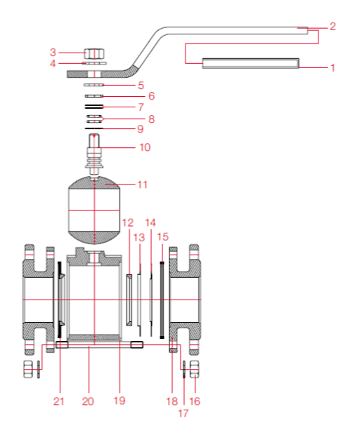
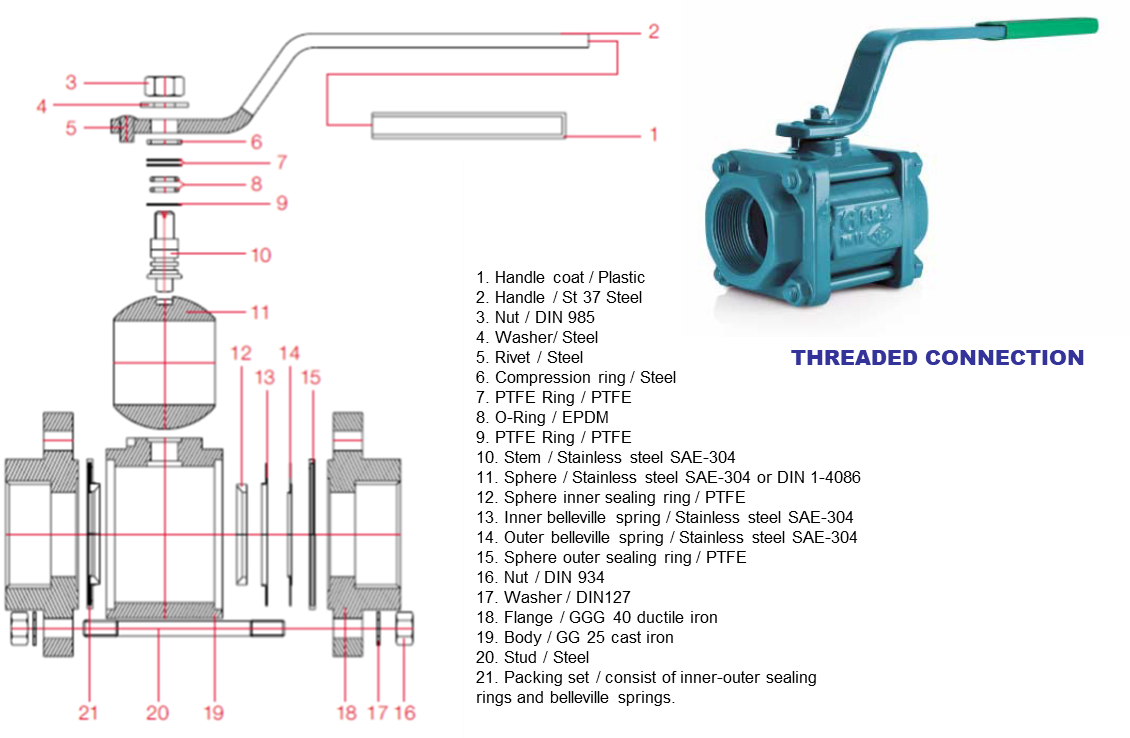
1. Handle coat / Plastic
2.Handle / St 37 steel
3.Nut / DIN 985
4.Washer/ Steel
5. Limiting Flange / Steel
6. Compression Ring/ Steel
7. PTFE Ring / PTFE
8. O-Ring / EPDM
9. PTFE Ring / PTFE
10.Stem / Stainless steel SAE-304
11. Sphere / Stainless steel SAE-304 or DIN 1-4086
12. Sphere inner sealing ring / PTFE
13. Inner belleville spring / Stainless steel SAE-304
14.Outer belleville spring / Stainless steel SAE-304
15.Sphere outer sealing ring / PTFE
16.Nut / DIN 934
17. Washer / DIN 127
18. Flange / Cast iron or Ductile Iron
19. Body / Cast iron or Ductile Iron
20. Stud / Steel
21. Packing Set / consist of inner-outer sealing
rings and belleville springs.
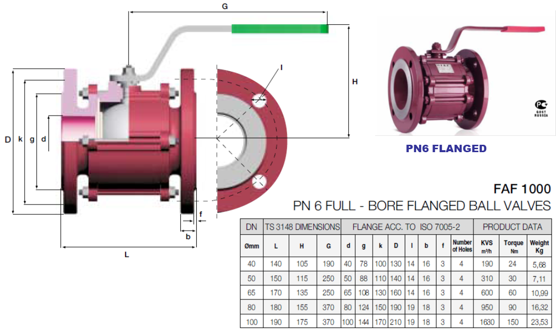
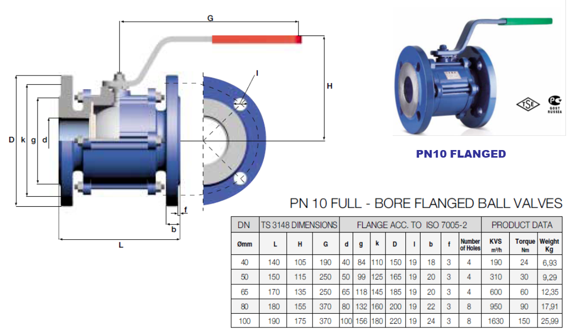
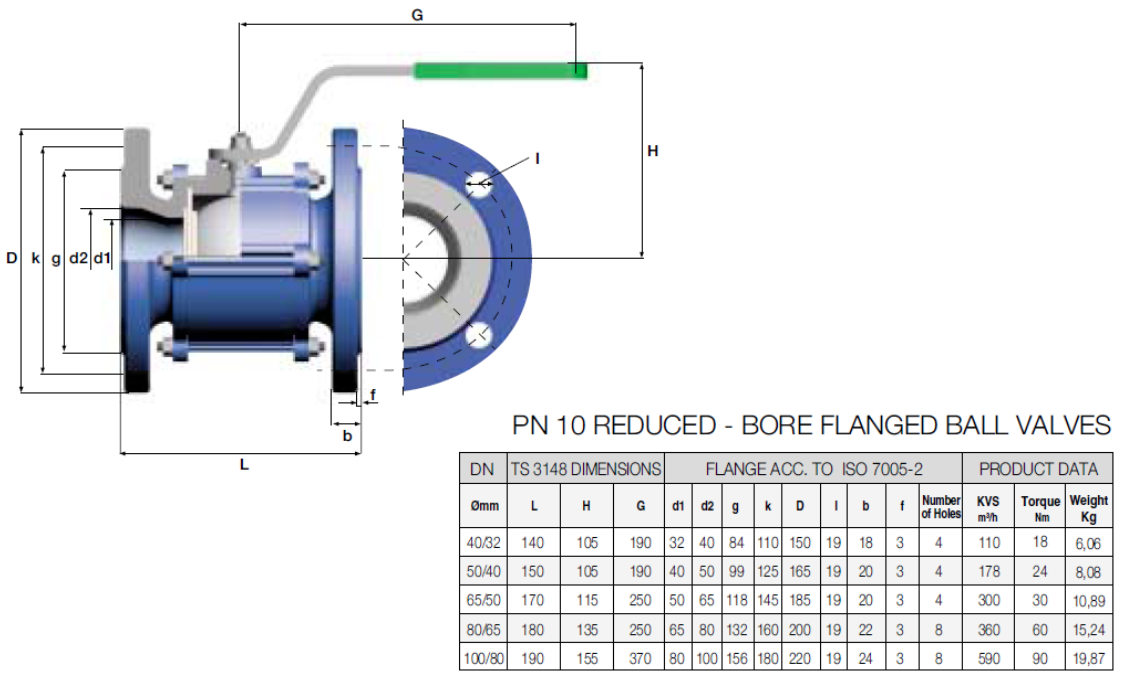
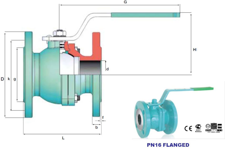
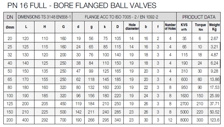
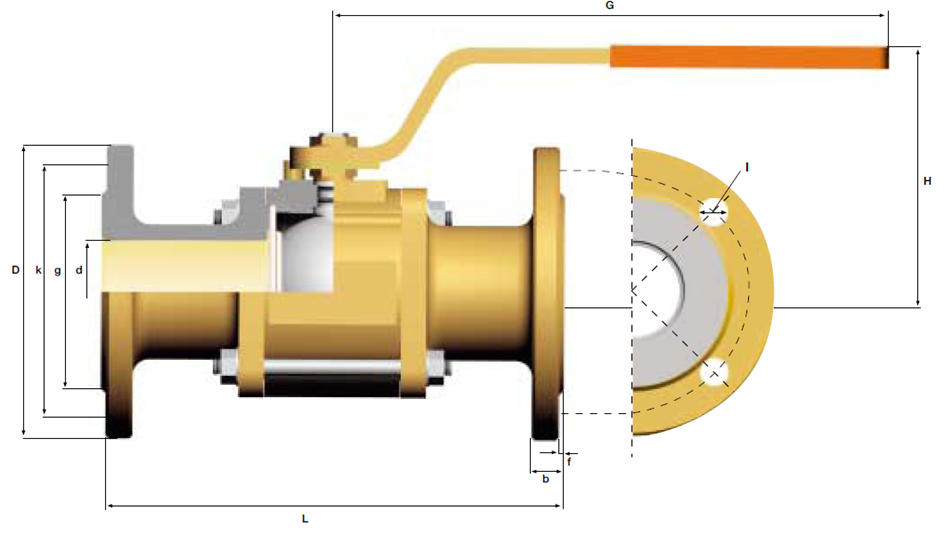
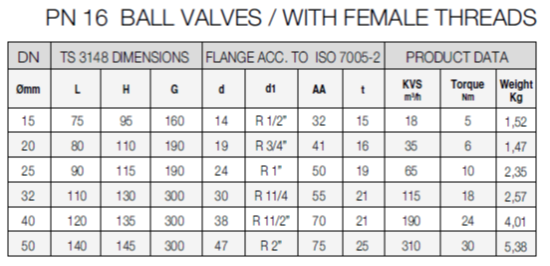
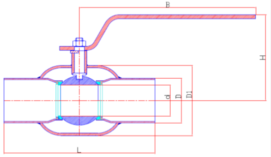
Dimensions
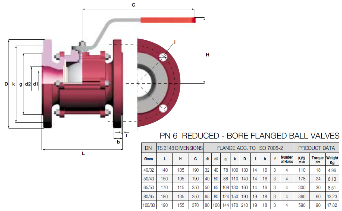
Dimensions
Dimensions
Dimensions
PRODUCT FEATURES
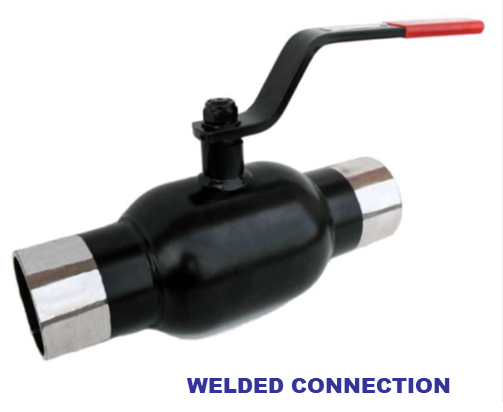
• One piece body
• Blow-out proof stem
• High precision ball made of Stainless Steel DIN1.4086
• Body and piping material can be chosen from the wide range of steel piping materials according to customers’ requirements. Standard production with St37 Steel
• Quarter-turn operation
• Reduced bore
• Bi-directional
APPLICATIONS
Steam, cold water, hot water and
pressurized hot water installations,
chemical fluids, compressed air, etc.
TEMPERATURE: Max. 200 oC
PRESSURE: Max. 25 bars
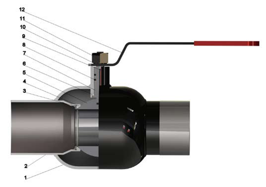
1. Body, St 37
2. Connecting Pipe, St 37
3. Base, St 37
4. Ball Seal Packing AISI 420, Silicone, PTFE
5. Ball, DIN1.4086
6. Trust Washer, PTFE
7. Stem, 303 SS
8. O-ring, Viton
9. Stem bolt, AISI 420
10. Nut Washer, DIN 439
11. Hexagon Nut, DIN 934
12. Handle, St37
Maintenance Instructions
DISMOUNTING :
- Make sure that there is no fluid supply on the line where the valve is detached.
- Unscrewing the connection bolts and nuts in opposite pairs, detach the valve from the line.
- Unscrew in opposite pairs the nuts (16) of the studs (20) connecting the flanges and the body. Remove the washers
(17) and detach the body (19) from two flanges.
- Turn the handle (2) to closed position and remove the packing set (21) located in two sides.
- Push the sphere (11) slightly to remove it from the body.
- Unscrew the nut (3) on the handle. Remove the washer (4), handle (2), limiting flange (5), compression ring (6),
PTFE Rings (7), respectively from the stem. To remove the stem (10) press on it to drop inside the body.
- Remove the O-Rings (8) on the stem.
- Remove the PTFE Ring (9) on the stem.
INSPECTION AND CLEANING :
- Replace the sphere if excessive scratches and nicks are noted. If lime stains are observed on the sphere, clean
the sphere in water with wet sandpaper (400). While maintenance processes, avoid damaging the sphere processed
in 0.01 mm sensitive CNC machines.
- Packing set located on two sides of the body consists of belleville spring (13-14) and inner-outer sealing (12-15)
elements. If any crack, tear or cut observed on the inner (12)-outer (15) rings or if the belleville spring and rings are
deformed, request a new packing set from our company.
- PTFE ring and O-Rings on the stem must be replaced with new ones.
- Epoxy coultar priming coat is applied on the inner surfaces of the body and the flanges, however, if there exists
oxidations, these regions must be cleaned and repainted with similar coatings. (Do not paint the stem hole
and the flange-packing set compression surface).
- Inspect stud threads and nuts. Replace deformed or rusty parts.
- Clean all materials carefully and proceed to mounting.
MOUNTING :
- Place PTFE Ring (9) and O-Rings (8) of the stem (10). Lightly grease the surfaces of the O-Rings. Mount the
stem through body cavity without damaging O-Rings. On the upper side, mount the PTFE Rings, compression
ring (6), limiting flange (5), handle (2), washer (4) and the nut (3), respectively. Tighten the nut to finish the mounting
of the stem.
- Turn the handle to closed position, place the sphere inside the body as the canal on the sphere will be parallel to
the stem key. Check if the sphere can freely move forward, back, up and down inside the body cavity.
- Mount the packing set on two sides of the body as the inner rings will face the sphere.
Position the mounted body between two flanges, place studs, nuts and washers and tighten the nuts in opposite
pairs to eliminate the gaps.
Note: It is highly recommended to open and close our valves once in 15 days for a longer service life after installation.
DİĞER ÜRÜNLER

